Open Electric Co.,Ltd.
Open Electric Co.,Ltd.
Products
Search Catalog
|
|||||||||||||||||||||||||||||
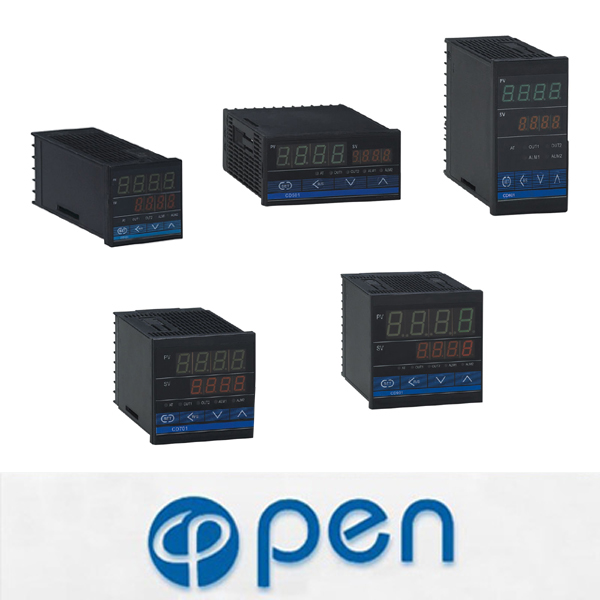
CD series Intelligent digital temperature controller
Iheating /Cooling control
Iauto adjusting function
Idigital communication
Ibig screen LED display
Iindustrial standard microcomputer processor
Model name:
|
① Outline dimension |
See the outline dimension picture |
|
|
② Control Mode |
F:PID operation andauto calculating(reverse operation) |
D:PID operation and auto calculating (Forward operation) |
|
W:hating/cooling PID operation and auto calculating (cooling water)*1 |
A: hating/cooling PID operation and auto calculating (cooling water)*1 |
|
|
③ Input mode |
Refer to input Range Table |
|
|
④ Range Code |
Refer to input Range Table |
|
|
⑤ First control output(OUT1) (Heating side) |
M:Relay contact output V:Voltage impulse output T:Thyratron output |
8:Current output(IC4-20mA) G:Thyratron driving&triggering output |
|
⑥ Second control output(OUT2)(Cooling side)*2 |
No mark:when the control mode is F or D M: Relay contact output V:Voltage impulse output |
T:Thyratron output 8:Current output(IC4-20mA)
|
|
⑦ First alarm (ALM1) ⑧ Second alarm(ALM2) |
N:no alarm A:Upper-limit bias alarm B:Lower-limit bias alarm C: Upper/Lower-limit bias alarm D:alarm in area E:Standby upper-limit bias alarm attached F: Standby lower-limit bias alarm attached G: Standby upper/lower-limit bias alarm attached H: Upper-limit input &#118alue alarm |
J: Lower-limit input alarm K: Standby upper-limit input alarm attached L: Standby lower-limit input alarm attached P:Heater breakage alarm(CTL-6)*3 S: Heater breakage alarm(CTL-12)*3 R:Control line breakage alarm*4 V:Upper-limit set &#118alue alarm W:Lower-limit set &#118alue alarm |
|
⑨ Communication*5 |
N:No communication |
5.RS-485(two-wire system) |
|
⑩ Water-proof/dust-proof |
N:NO water-proof/dust-proof |
1:with water- proof/dust-proof |
Note:
*1 W or A Type has no auto asjust funcion.
*2 second alarm output (OUT2) Second alarm(ALM2)
*3 can’t be set first alarm
*4 Control ring lie breakage can choose one only from alarm1 and alarm2
*5 Only CD series has the communication
Outline dimension:
|
Thermocouple Input(TC) |
Input type |
Set range |
Input type |
Set range |
|
K |
0 to 1372℃(0 to 2502℉) |
J |
0 to 1200℃(0 to 2192℉) |
|
|
R |
0 to 1769℃(0 to 3216℉) |
S |
0 to 1769℃(0 to 3216℉) |
|
|
B |
0 to 1820℃(0 to 3308℉) |
E |
0 to 1000℃(0 to 1832℉) |
|
|
N |
0 to 1300℃(0 to 2372℉) |
T |
-199.9 to +400.0℃ (-199.9 to 752℉) |
|
|
W5Re/W26Re |
0 to 2320℃(0 to 4208℉) |
PL |
0 to 1390℃(0 to 2534℉) |
|
|
L |
0 to 900℃(0 to 1652℉) |
U |
0 to 900℃(0 to 1652℉) |
|
|
RTD inputPt |
100Ω(JIS/IEC) |
-199.9 to +649.0℃ (-199.9to 999.9℉) |
JPT100Ω(JIS) |
-199.9 to +600.0℃ (-199.9to 999.9℉) |
|
Voltage input |
0 to 5 VDC 1 to 5 VDC |
-1999 to +9999 (programmable range) |
||
|
Current input |
0 to 20mADC 4 to 20mADC |
-1999 to +9999 (programmable range) |
||